Innovative, Simple, Efficient, Full-Scale Tested
Invisible Connections
Invisible, gravity load connectors designed to eliminate aesthetically undesirable corbels, haunches, ledges or daps for clean, elegant connections between beams, staircases, slabs, double tees, and other precast/prestressed concrete structures.
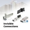
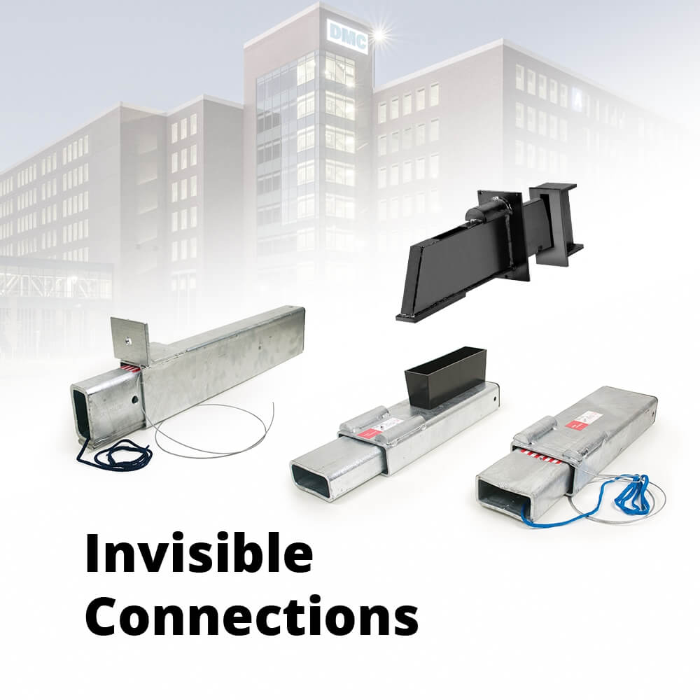

Invisible Connections
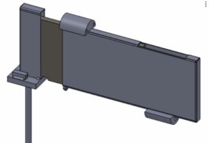
The Shooter Double Tee Connection
An invisible, gravity connection designed to eliminate the need for aesthetically undesirable corbels, haunches, or daps when building a precast/prestressed concrete structure incorporating double tees … LEARN MORE
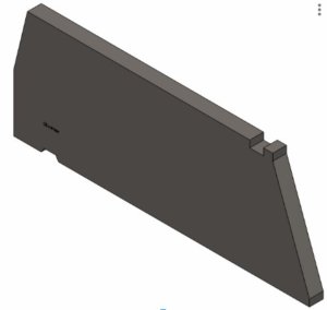
BSF Beam Connector
A hidden beam-end connection for gravity loads that eliminates the need for projecting column corbels. It provides a simple, efficient connection that allows the designer new freedom in creating clean, elegant lines in the completed precast/prestressed concrete structure … LEARN MORE
TSS/RVK Stair Connections
Hidden, telescopic gravity connections primarily used for connecting precast stairs and landings; two options offering clean streamlined aesthetics by eliminating unsightly corbels or ledges… LEARN MORE
The Shooter Double Tee Connection
An invisible, gravity connection designed to eliminate the need for aesthetically undesirable corbels, haunches, or daps when building a precast/prestressed concrete structure incorporating double tees … LEARN MORE
BSF Beam Connector
A hidden beam end connection for gravity loads that eliminates the need for projecting column corbels. It provides a simple, efficient connection that allows the designer new freedom in creating clean, elegant lines in the completed precast/prestressed concrete structure … LEARN MORE
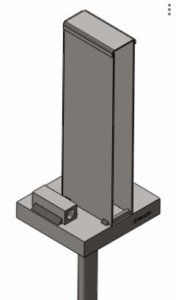
RVK/TSS Stair Connections
An innovative solution to the age-old question of how to connect precast concrete staircases. It is a standard prefabricated connection used between stair landing and wall, precast into concrete stairways … LEARN MORE
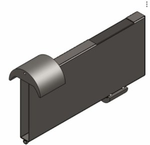
RVK/TSS Stair Connection
Hidden gravity connections for precast stairs and landings
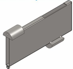
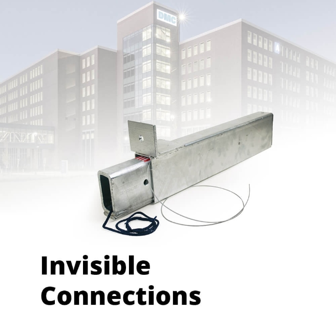
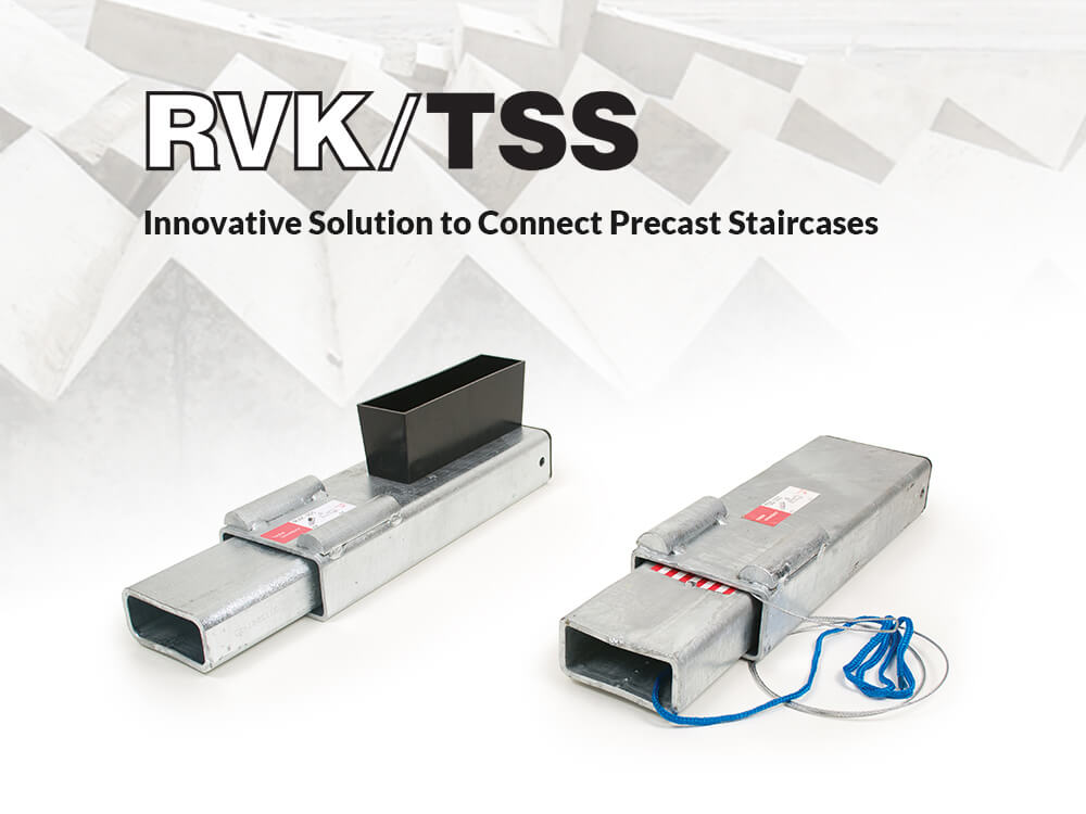
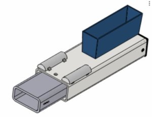
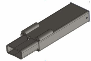
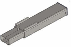
The TSS and RVK are hidden gravity connections for precast stairs and landings. Both are telescopic solutions where the unit is cast into the precast concrete and when erected, an inner tube is pulled out to fit in a receiving pocket in a support wall or beam. The design methodology for the TSS & RVK are identical with the TSS being completely hidden in the concrete and not exposed at the surface like the RVK, making it an ideal solution for conditions where the precast surface is exposed.
- No onsite welding and minimal onsite casting is necessary
- Offers clean streamlined aesthetics by eliminating unsightly corbels or ledges
- Extensive published test reports to validate performance and recommended capacities
- User guidelines available below for engineering, purchasing, production and erection
Overview
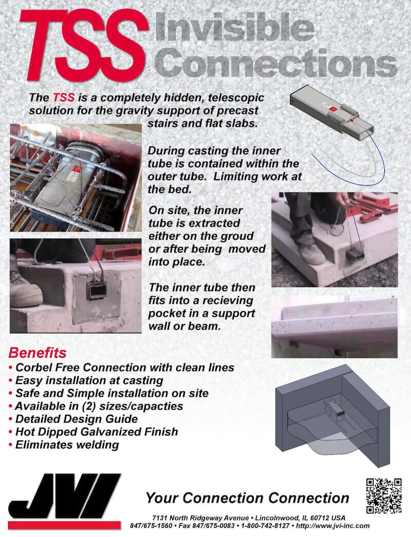
The TSS and RVK are hidden gravity connections for precast stairs and landings. Both are telescopic solutions where the unit is cast into the precast concrete and when erected, an inner tube is pulled out to fit in a receiving pocket in a support wall or beam. The design methodology for the TSS & RVK are identical with the TSS being completely hidden in the concrete and not exposed at the surface like the RVK, making it an ideal solution for conditions where the precast surface is exposed.
In 1994, JVI was approached by PARTEK (now SPENNCON CORP.), a Norwegian firm, to market and sell the BSF framing connection system & the RVK stair connection. These two hidden connections offer clean streamlined aesthetics by eliminating unsightly corbels or ledges. These are valuable tools in helping the architect choose precast over cast-in-place. Consideration for the use of these products can be best accommodated early in the design phase of a project.
TSS Invisible Stair/Slab Connection
Cord operated, sliding inner. No visible markings on landing top surface – ideal for landings without screed toppings.
- Safe and Simple Installation on site
- Eliminates welding
- Corbel free connection with clean, elegant lines
- Available in (2) capacities/sizes
- Reduces stair impact sound
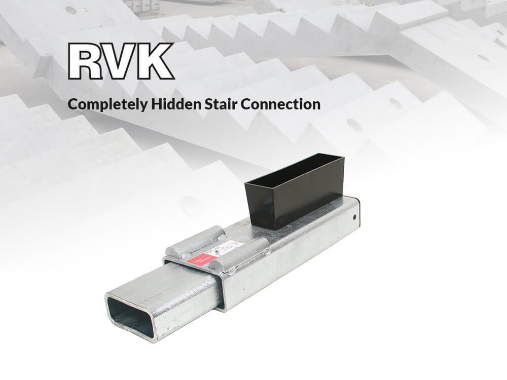
RVK Stair Connector
Operated by a bolt mechanism from above landing. Cost-effective, rugged solution ideal for screeded landings.
- Quick clean hidden connection
- May be cast in up or down positions depending on the required finish of the surfaces
- JVI Masticord pad reduces ‘stair noise’
Other Benefits
- The Architect gains a smooth obstacle-free soffit with no supports on show
- The Engineer gains a robust, simple and efficient connection, which can also be used to satisfy robustness
- The Insitu Contractor does not need to incorporate connections into the wall requiring tight tolerance
- The Precaster keeps control of the connection within the factory, with no need for specialist operations on site
- The Main Contractor gains reduced crane hook-time requirements, and rapid provision of access stairs


Shooter Connector
An invisible, gravity connection designed for clean, elegant connections with double tees
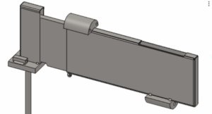
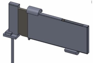
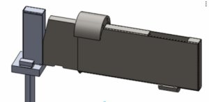
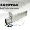
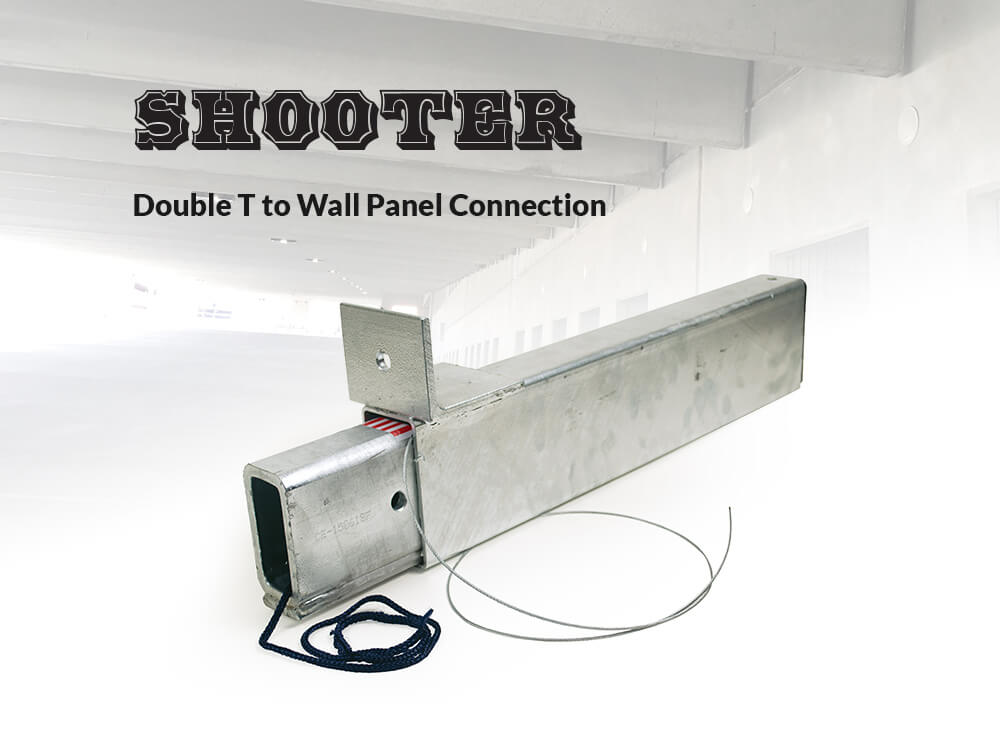
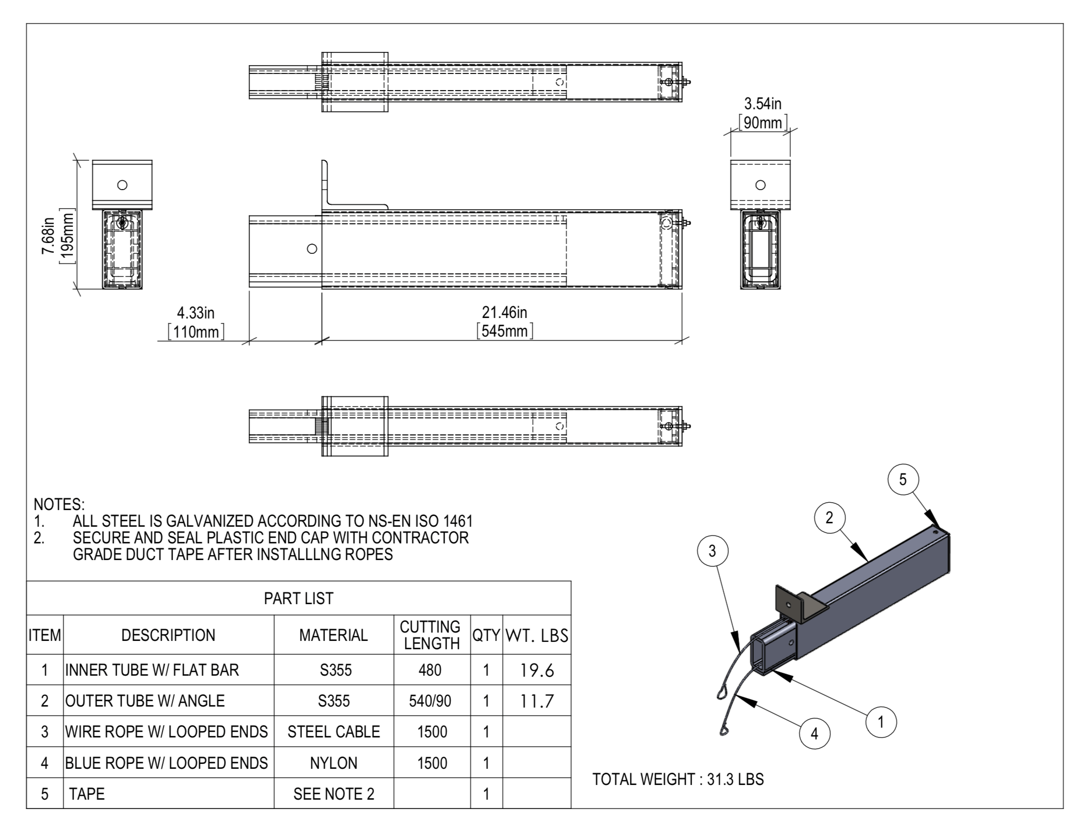
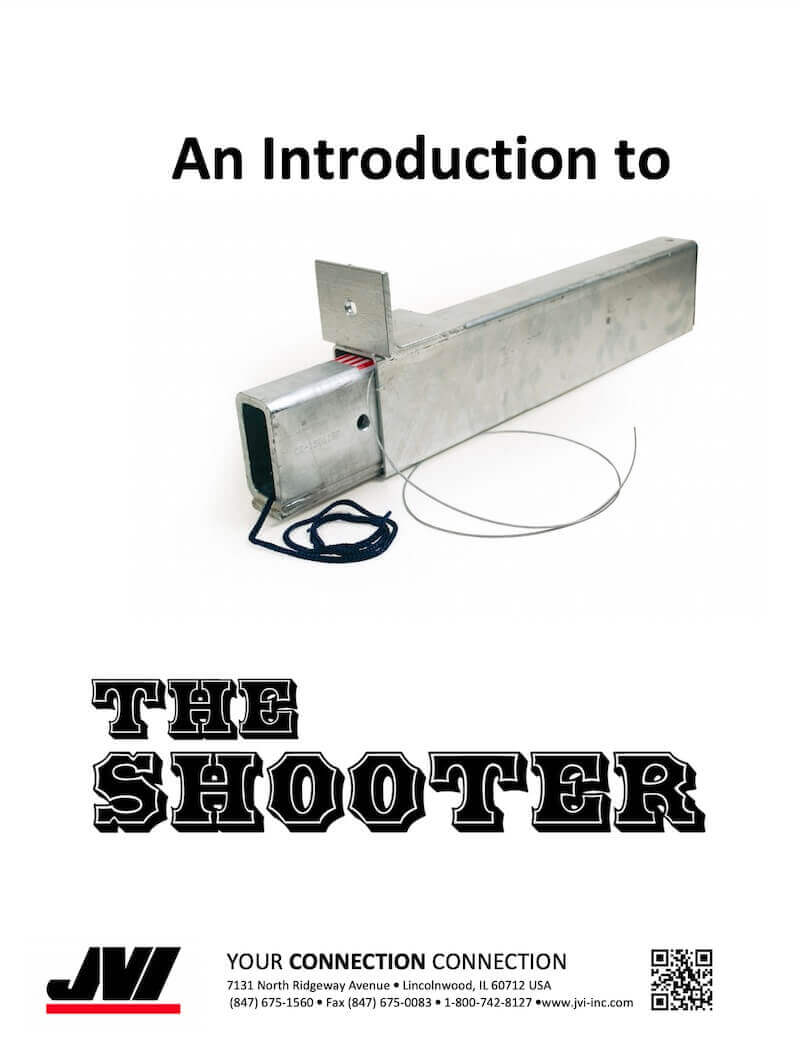
The ShooterTM is an invisible, gravity connection designed to eliminate the need for aesthetically undesirable corbels, haunches, or daps when building a precast/prestressed concrete structure incorporating double tees.
- Simple, efficient connection that creates clean, elegant lines by eliminating weld on corbels and ledges, reducing the size of the pocket in the spandrel, and eliminating dap forming, bearing plate, and reinforcing
- Extensive published test reports to validate performance and recommended capacities
- User guidelines available below for engineering, purchasing, production and erection
Overview
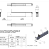
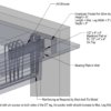
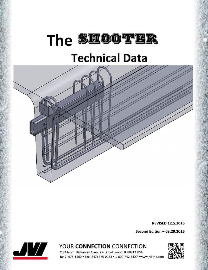
The ShooterTM is an invisible, gravity connection designed to eliminate the need for aesthetically undesirable corbels, haunches, or daps when building a precast/prestressed concrete structure incorporating double tees. More specifically, it is a tube within a tube which is cast into the ends of the double tee stems at their widest point. The inner tube is recessed during casting and extended at erection into a receiving pocket in a spandrel, wall, or beam. Full scale test results have indicated that the ShooterTM has a mechanical design strength in excess of 40,000 lbs.
Benefits
- Eliminates dap forming and reinforcing
- Eliminates weld on corbels and ledges
- Reduces torsion on supporting members
- Reduces the size of the pocket in the spandrel
- Simplified erection does not require “diving” of double tees into pockets
- Allows for axial volume movements due to creep, shrinkage and temperature change
- Can increase ceiling height or reduce overall height of the structure
- Entire unit hot-dipped galvanized
- Full-scale tested solution to verify design methodology
- Comprehensive User Guidelines Available
- Downloadable Drawings And Models

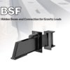
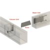
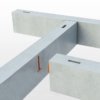


BSF Connector
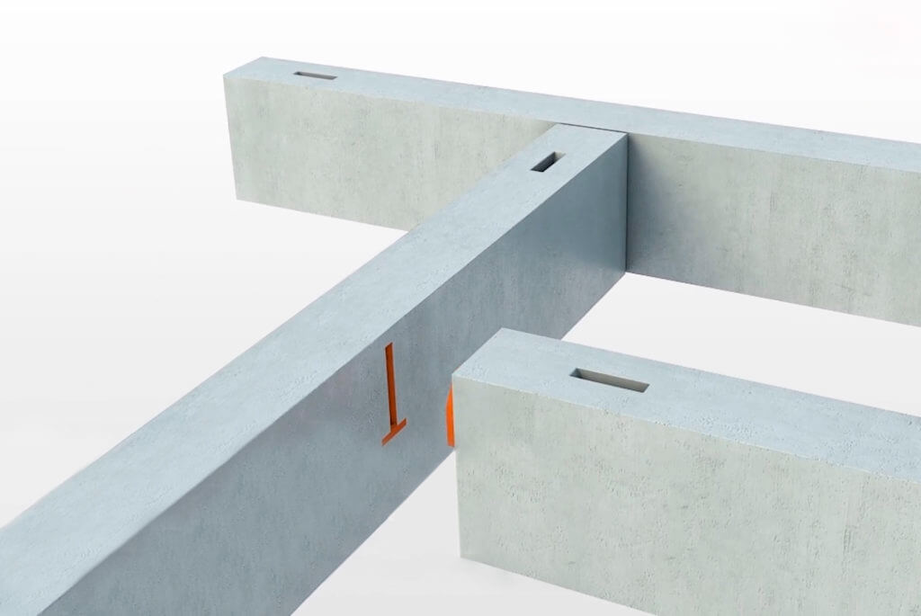
A hidden beam end connection for gravity loads that eliminates the need for projecting column corbels.
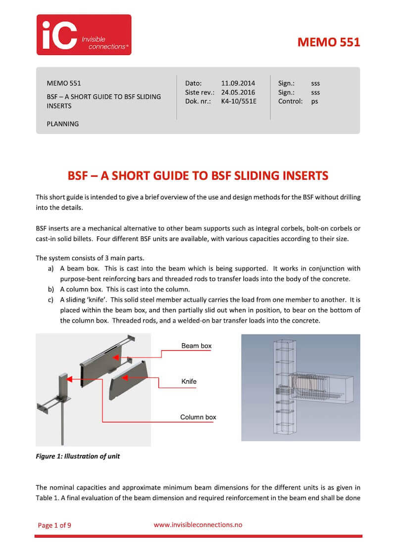
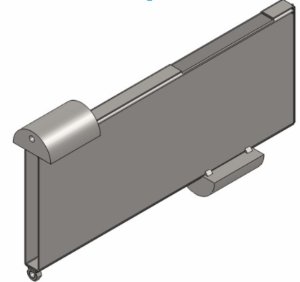
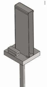
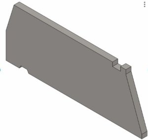
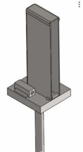
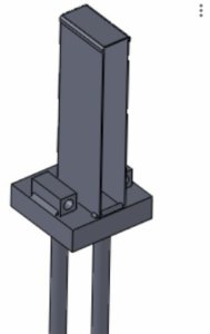
The BSF connection is a hidden beam end connection for gravity loads that eliminates the need for projecting column corbels. It provides a simple, efficient connection that allows the designer new freedom in creating clean, elegant lines in the completed precast/prestressed concrete structure. The BSF connection can be used in all types of building structures where beams frame into columns, such as office buildings, hotels, parking structures, schools, sports stadiums, and other similar structures.
- A mechanical alternative to other beam supports such as integral, or cast-in solid corbels
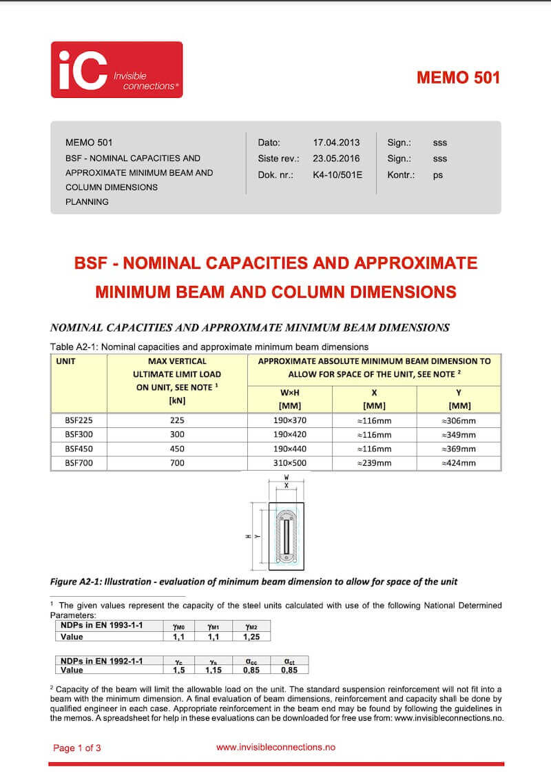
- Designed for heavy-duty beam supports, with capacities from 225 kN to 700 kN
- Loads up to 1400 kN supported when using pairs of connectors
- Four different BSF units are available, with various capacities according to their size
- Extensive published test reports to validate performance and recommended capacities
- User guidelines available below for engineering, purchasing, production and erection
Overview
The BSF connection is a hidden beam end connection for gravity loads that eliminates the need for projecting column corbels. It provides a simple, efficient connection that allows the designer new freedom in creating clean, elegant lines in the completed precast/prestressed concrete structure. The BSF connection can be used in all types of building structures where beams frame into columns, such as office buildings, hotels, parking structures, schools, sports stadiums, and other similar structures.
In 1994, JVI was approached by PARTEK (now SPENNCON CORP.), a Norwegian firm, to market and sell the BSF framing connection system & the RVK stair connection. These two hidden connections offer clean streamlined aesthetics by eliminating unsightly corbels or ledges. These are valuable tools in helping the architect choose precast over cast-in-place. Obviously, consideration for the use of these products can be best accommodated early in the design phase of a project.
Benefits – Construction
- Clean straight lines
- Completely hidden connection
- Easily used with round columns
- Easily protected against fire and corrosive elements
- Quick erection…no bolting or welding on site
- Flexibility in column production sequence
- 4 Capacities
Benefits – Time & Money
- Reduces space requirements for storage and transport
- Lowers transport costs
- Saves time in design and drafting
- Efficient production technique
- Standard hardware inventory